Turning on Intel Edison with mini breakout board
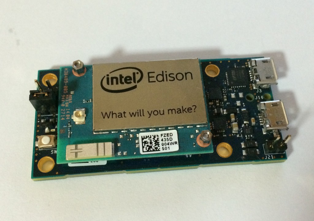
When you got the Intel Edison and unboxed it, you can be very embarrassed(especially with the mini breakout board). Only Edison module, mini breakout board and some nuts are all in the box. No cable, no manual included.
So first of all, I recommend you to read these documents from Intel.
– Edison module: https://communities.intel.com/docs/DOC-23158
– Breakout Board: https://communities.intel.com/docs/DOC-23252
– Arduino Board: https://communities.intel.com/docs/DOC-23161
and you can find more documents including schematic here.
(It is hard to say that every information about edison is there, but Intel quite frequently adds and updates the documents.)
In this post, I explain how to connect the power to Edison and turn it on.
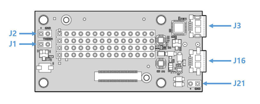
On the topside of Breakout board, you can see some jumpers. And with these jumpers, you can supply the power to Edison with 4 methods.
0. Before you start
Assemble your edison kit. Place Edison module on mini breakout board. Press down edison module and check the 70 pin connectors are well connected. Then tighten two hex nuts onto two screws softly.
1. Using USB cable
This is most simple and familiar way. Breakout board has two USB ports, J3 and J16. J3 is leading from the UART-USB converter chip, so it is for accessing the linux console.
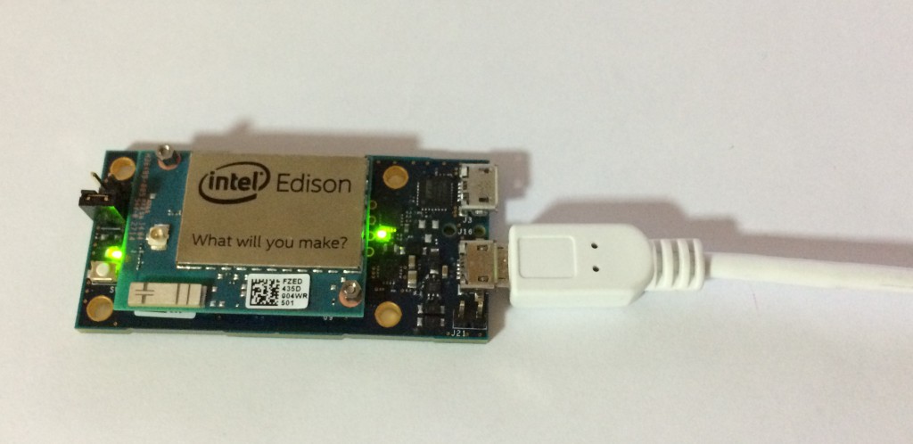
J16 is an USB On The Go(OTG) port. You can use a USB cable with micro-B connector(most common usb cable, the same one for android phones). When Edison is connected to a PC with the cable, the PC will be the host and Edison will run as a client. Also the PC will supply the power to Edison and Edison will be turned up instantly.
If you have a USB cable with micro-A connector(aka. OTG cable), you can use the cable to connect your Edison with other USB device. In this case, Edison becomes USB host and supply power to the device. Of course in this case, you need other power source for Edison instead of J16.
2. External power supply
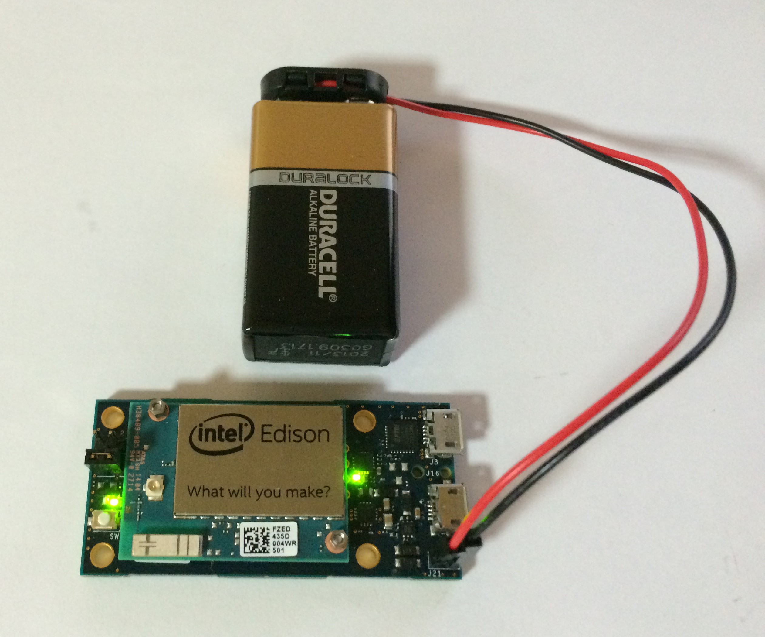
With J21, you can supply DC power directly to Edison. The input voltage range is from 7V to 15V, so you can choose any power source you want. I used a 9V battery in this post. Be careful about the polarity. The pin close to the edge is for the ground(GND, black line), and the inner one is for the positive(+, red line).
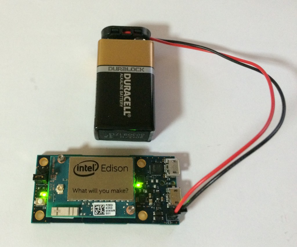
3. Lithium battery
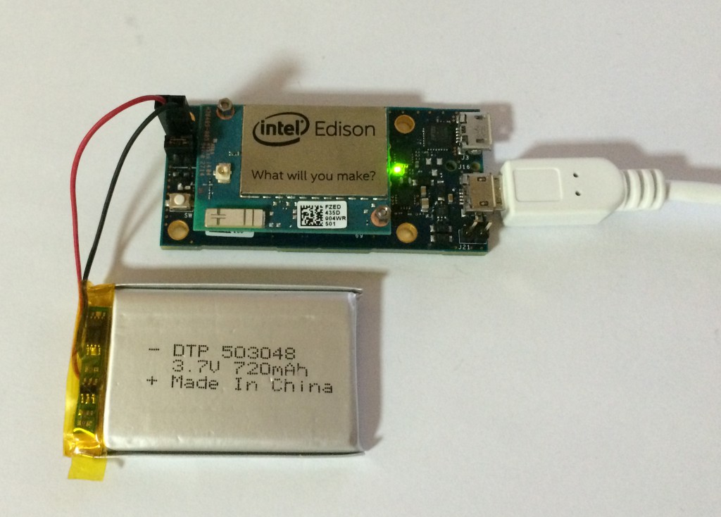
You can use J1 and J2 with Lithium battary(Lithium Ion or Polymer). Connect battery’s red line to J2’s left pin(the one close to the edge) and black line to right pin. If the battery is charged enough, Edison will be switched up. The Breakout board contains lithium battery charging circuit, so you don’t need to worry about how to charge the battery. When Edison is connected to USB power or external power source, the Lithium battery will be in charging. However the mini breakout board has no ADC(Analog-digital converter), thus it is impossible to monitor the battery’s voltage level and battery remains.
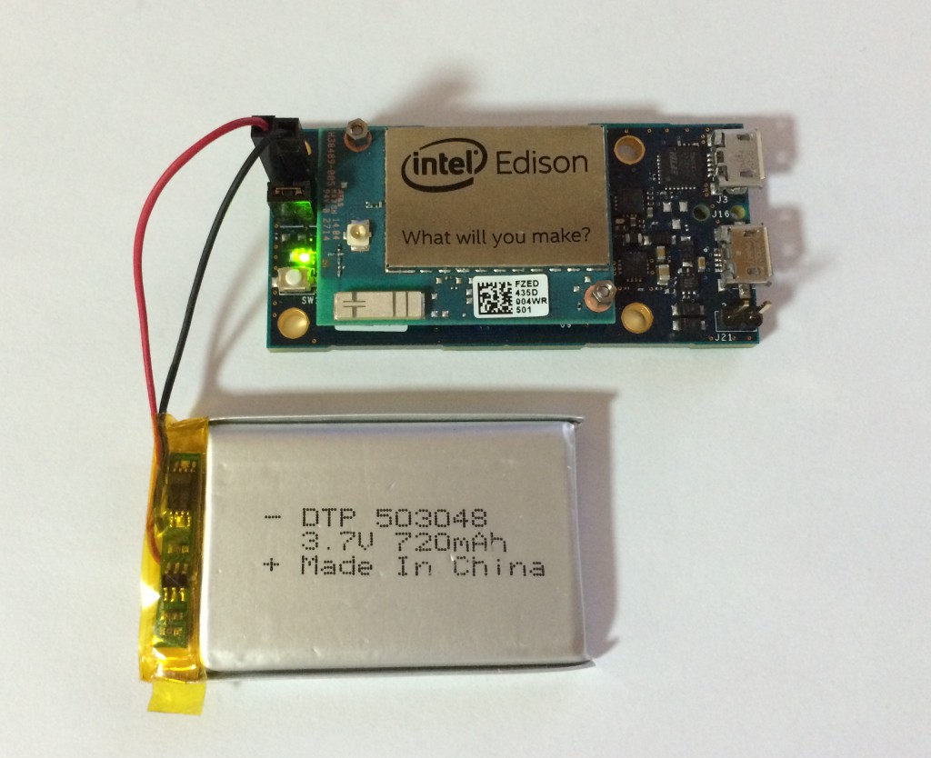
Another pin J1 is for connecting with thermistor of lithium battery. If your battery has additional line for thermistor, you can connect it to J1. If not, just remain the pin as it was with the jumper.
4. External power supply2(DC power socket)
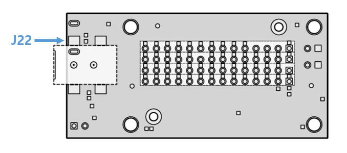
J22 is located on the bottom side of the breakout board. You can solder a DC power socket to J22 and supply power through the socket. Like J21 pin, the input voltage range is from 7V to 15V. If you are going to use AC/DC adaptor in your Edison project, this is worth consideration.
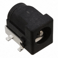
In addition, you can supply power using the power pin holes of the breakout board. Read the hardware guide. https://communities.intel.com/docs/DOC-23252
Power button and LEDs
Breakout board has two LEDs to check power status.
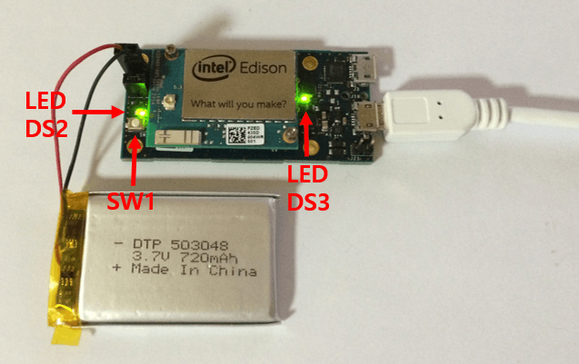
DS2 indicates the power status of Edison module. When DS2 is on, it means Edison is on and running. If DS2 is off, Edison module is off. DS3 shows the status of external power and charging status. When breakout board is connected to the power source with USB or J21, DS3 lights up which means external power source is connected and can charge lithium battery. When the lithium battery is fully charged, DS3 will be turned off.
The button, SW1, is for changing power mode of Edison. When you press the button momentarily, Edison will be sleep state. By pressing it again, you can wake Edison up. If you press the button for some seconds(>7 secs), Edison will be turned off. You can see DS2 is also off. To turn on Edison module, press the button for some seconds(>7 secs) again.
I hope this post help the starters of Edison to choose the power source as you want in your projects.
[gard]
See also
One Comment
Leave a Comment
You must be logged in to post a comment.
Thanks for sharing what you have learned about the Edison. It amazes me that Intel has published so little.